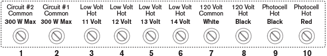
The PX Series Transformer terminal block consists of 9 or 10 terminal lugs depending upon the transformer model. The PX 300 Series Transformer includes one “common” lug, an 11, 12, 13, and 14 volt “hot” lug and four lugs wired to the line voltage side of the transformer. The PX 600 Series Transformer terminal block has two “common” lugs, four low voltage “hot” lugs and four line voltage lugs. The PX 900 Series Transformer terminal block has three “common” lugs, a 12, 13, and 14 volt “hot” lug and the four line voltage lugs.
Each of the “common” lugs in any of the PX Series Transformers has a maximum wattage capacity of 300 watts or 25 amps. Each of the “hot” lugs in any of the PX Series Transformers has a maximum wattage capacity equal to the maximum load of the transformer. In other words, the 13 volt tap on a PX 600 Transformer can handle up to 600 watts of load. But the commons can handle only up to 300 watts each.
Terminal block of a PX 600 Series Transformer
Number of cables in each lug
The PX Series Transformer has the industry’s largest terminal block lugs. You will be able to easily fit many cables into each voltage lug should your installation call for it. (We have actually installed over ten 12 gauge cables into a single lug.)
Common lugs
One conductor from each cable run coming from the lights to the transformer must be connected to one of the common lugs. As previously stated, each common lug can handle a maximum capacity of 300 watts or 25 amps of load. The other conductor will be installed into the hot lug that provides the optimum voltage for each circuit.
Choosing the proper “hot” voltage lug
Choosing the proper “hot” voltage lug in which to install the conductor is determined by the circuit’s voltage drop. If a circuit’s voltage drop is calculated to be about 3 volts, install the “hot” side of the cable into the 14 volt tap to assure proper voltage at the lamp. (14 volts minus 3 volts = 11 volts) Note: The voltage reading at each “hot” lug will vary depending upon the incoming voltage provided by the 120 volt receptacle. If the receptacle reads 128 volts, it is not uncommon for the 12 volt lug on the transformer to read 12.6–12.9 volts. On the other hand, if the receptacle is reading only 116 volts, the 12 volt lug may only read 11.8–12.2 volts. Always verify both high voltage and low voltage readings with a digital voltmeter. (See page 11) Fine tune each circuit by using a digital voltmeter. Lamps perform best when supplied between 10.5 and 11.5 volts. Before waterproofing wire connections, take a voltage reading at the first and last fixture on each circuit. If the voltage reading at the first fixture on the circuit reads less than 10.5 volts, move the conductor up to a lug that will provide approximately 11 to 11.5 volts. (Example – voltmeter reads 9.6 volts at the first fixture on the circuit and the conductor is was installed on the 11 volt lug. Move the conductor to the 12 or 13 volt lug and it will now read 10.6 or 11.6 volts.) If the voltage reading exceeds 12 volts, move the conductor down to a voltage tap that will meet the desired voltage range (10.5–11.5 volts).
Circuit breakers
All PX Series Transformers are protected with high quality circuit breakers located on the face of the transformer. The PX 300 has a single 25 amp circuit breaker. The PX 600 has two 25 amp circuit breakers and the PX 900 has three 25 amp circuit breakers. These circuit breakers should always remain in the “On” position; otherwise the system will not operate. They are NOT to be used as “On/ Off” switches. Switching the transformer should be performed by other means. The circuit breakers are safety switches which will trip if the system experiences a short in the cabling or a system overload. If the circuit breakers are tripping, refer to the troubleshooting section of this guide. Once the problem has been resolved, the circuit breakers can be manually reset.
Internal circuit breaker
As an additional safety measure, each PX Series Transformer has an internal thermal overload circuit breaker that automatically shuts the system down should it be subjected to excessive heat. The internal circuit breaker cannot be manually reset. Once the transformer cools off (approximately 40 minutes), the internal breaker will reset and the system will reengage.